Bare-metal firmware for Vybrid's asymmetrical multicore architecture
September 17, 2014

In the previous article, Valter Minute discussed the architecture in general and the advantages of asymmetric (also known as heterogeneous) multicore...
In the previous article, Valter Minute discussed the architecture in general and the advantages of asymmetric (also known as heterogeneous) multicore SoCs. There are several options when it comes to the operating platform for the secondary Cortex-M4 core: The example discussed in Valter’s article uses eCos RTOS, Freescale promotes its own RTOS MQX.
However, depending on the application, one might even prefer a bare-metal solution, e.g. to port a legacy firmware or for its simplicity. However, there are also disadvantages, the most prominent being missing drivers for peripherals. This article shows some technical pitfalls when creating a custom-made, bare-metal firmware for the Cortex-M4 core of Vybrid.
As an example environment, I decided to contribute Vybrid support to the open-source firmware library libopencm3. The library is licensed under LGPL version 3, hence linking closed source application against the library is explicitly permitted. Despite its name, this library also supports various Cortex-M4 microcontroller, hence its a quite good fit for Vybrid’s Cortex-M4 core. Using the library we can leverage the support for the Cortex-M4 core peripherals such as the system tick timer or the nested interrupt controller. One might argue that using a library is not really bare-metal, however since almost all components of the library are completely optional, it comes much closer to bare-metal than using a full fledged RTOS.
The code is not yet merged into the upstream project, but already available from Github (switch to fsl-vf6xx branch): https://github.com/falstaff84/libopencm3 and https://github.com/falstaff84/libopencm3-examples. Detailed build instructions here: http://falstaff.agner.ch/2014/07/10/libopencm3-bare-metal-vybrid-examples/
Memory and flash
The first and most prominent difference between a standard microcontroller and Vybrid’s Cortex-M4 is the different memory and flash architecture. On a microcontroller, the non-volatile memory is usually accessible in the controller’s linear address space allowing it to execute the firmware in place (XIP). On Vybrid, non-volatile memory usually isn’t implemented in a way that allows it to execute in place. Instead, the firmware is loaded from the storage media (e.g. NAND flash) into RAM by the main operating system (e.g. Linux) subsequently being executed by the Cortex-M4 core.
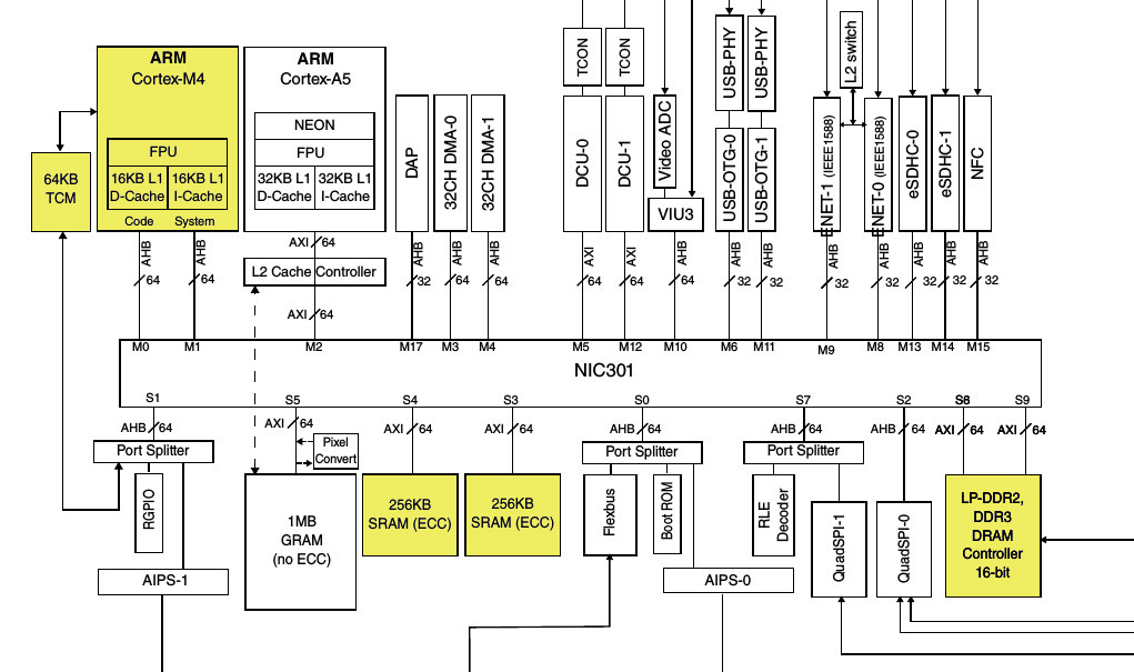
There are no less than three memory types available to run from: tightly coupled memory, on-chip memory (OC-RAM/SRAM), and external (DDR) memory. The tightly coupled memory (TCM) is the fastest memory available since it’s directly connected to the Cortex-M4 core. However, the available amount of memory is also quite limited. The on-chip memory, SRAM, is a popular choice since it offers a good trade-off in terms of size and speed. Freescale provides an extensive document discussing speed and recommendation of the available memory types (see AN4947, Understanding Vybrid Architecture).
Another aspect is the Cortex-M4′s Harvard like architecture that consists of two buses, one for data and one for instructions. In order to make sure the hardware uses those two buses accordingly, the memory map provides aliases to access the same memory location using the two buses:
OC-RAM Code-Bus: 0x1f000000-0x1f03ffff
OC-RAM System-Bus: 0x3f000000-0x3f03ffff
For optimal performance, this should be taken into account in the linker file’s memory description; the libopencm3 library defines two memory regions, the Code-Bus (pc_ram) and the System-Bus (ps_ram). In the following example, the available memory is split in half, 256K of RAM for each section. Since the addresses are aliases for the whole memory range, one can freely adjust the size of those two sections according to the projects need.
Linker control file snippet: examples/vf6xx/colibri-vf61/colibri-vf61.ld
MEMORY
{
    pc_ram (rwx) : ORIGIN = 0x1f000000, LENGTH = 256K
    ps_ram (rwx) : ORIGIN = 0x3f040000, LENGTH = 256K
}
In the sections part, we need to assign the locations of code-sections (text) and data-sections (e.g. bss) to those two memory regions.
Linker control file snippet: lib/vf6xx/libopencm3_vf6xx.ld
SECTIONS

{

    .text : {

        *(.vectors)   /* Vector table */

        . = ALIGN(0x400);

        *(.text.reset_handler)   /* Force reset handler at start */

        *(.text*)   /* Program code */

        . = ALIGN(4);

    } >pc_ram

...

    .bss : {

        *(.bss*)   /* Read-write zero initialized data */

        *(COMMON)

        . = ALIGN(4);

        _ebss = .;

    } >ps_ram

...

}
Vector table and entry address
Another important aspect is the vector (interrupt) table. On a Cortex-M4, the vector table is read from 0x00000000 on reset. On microcontrollers, this is usually located in the non-volatile memory. On Vybrid, the Cortex-M4 core is initially turned off. In the firmware’s initialization code, we can use the Vector Table Offset Register (VTOR) to define a custom location of the vector table. In the linker file above, the vector table is explicitly placed at the beginning of the firmware. The initialization code in lib/vf6xx/vector_chipset.c makes sure the VTOR register is set on start-up.
For Cortex-M4 microcontrollers, the entry point (also known as reset vector) is part of the vector table. This introduces a circular dependency on Vybrid, since we initialize the vector table from within the firmware code (the VTOR register is not accessible from the Cortex-A5 core). To solve this dilemma, the entry point (“reset vector”) for the secondary core is defined externally by a register of the system reset controller (SRC) module. For Freescale’s boot utility “mqxboot,” the boot implementation in the mcc kernel module run on the Cortex-A5 core makes sure this register is set accordingly. The user needs to pass the entry point as an argument to “mqxboot.” Note: The address needs to have bit 0 set to 1 to tell the CPU the target is Thumb code (refer also to the “Running Secondary Core” chapter of the reference manual).
For instance, to load the firmware demo.bin to SRAM and start it on the secondary core, one uses mqxboot on Linux running on the primary core:
mqxboot
mqxboot demo.bin 0x3f000000 0x1f000401
The load address needs to be accessible from the Cortex-A5. In this example, this is the start of the SRAM. However, the entry point address is the code bus alias available only for the Cortex-M4 core.
Clocks
Since the Cortex-M4 runs on the system clock derived from the Cortex-A5 core clock, it’s not a good idea to alter clocks from the Cortex-M4 side. However in order to calculate timings, reading the clock register to get the current speed is necessary. In libopencm3, the calculation logic is implemented under lib/vf6xx/ccm.c. The main clocks are the ARM core clock (ccm_core_clk), the Platform bus clock which is also the Cortex-M4 core clock (ccm_platform_bus_clk) as well as the IPS (peripheral) clock (ccm_ipg_bus_clk).
Communication
Another aspect is the communication infrastructure to communicate with the main operating system running on the Cortex-A5. The libopencm3 implementation currently has no support for communication. Probably the simplest communication implementation is defining a shared memory area which one can access from both sides (consider using a synchronization mechanism using exclusive load/store instructions LDREX/STREX). A bit more sophisticated would be an implementation of the Multi-Core Communication (MCC) component of the MQX RTOS. This component makes use of the hardware semaphore module (SEMA4) as well as one of the four CPU to CPU interrupts to notify the other CPU when new messages are available. One can download a recent MQX release (4.0.2 and higher) to get the source code of MCC (verify that the license covers your use case).
Conclusion
Porting or implementing a bare-metal firmware on Vybrid is possible and not very complex. After all, the Cortex-M4 inside Vybrid is still a Cortex-M4 core executing the ARMv7-M architecture. Beside the peripheral drivers, the linker file as well as initial setup code need some special consideration.